Tutorial 3, cylinders and spheres
In addition to the boxes presented in the previous tutorial, Tokamak is able to model the movement of two additional primitives: spheres and cylinders. This tutorial examines the properties of each, and how to set them up in a Tokamak simulation.
Spheres
Spheres are probably the simplest of all primitives to work with as they
only have a single property to describe their dimensions: their diameter. To
add a sphere to the simulation, the following code is used (in the
InitPhysics procedure of the tutorial code):
// Set the parameters for the spheres fMass = 100.0f; // Create some spheres for (i=0; i<SPHERECOUNT; i++) { gSpheres[i] = gSim->CreateRigidBody(); geom = gSpheres[i]->AddGeometry(); // Tell the geometry that we want a sphere and set its size geom->SetSphereDiameter(SPHEREDIAM); // Update the bounding information gSpheres[i]->UpdateBoundingInfo(); // Set the inertia tensor -- again we use the sphere diameter here gSpheres[i]->SetInertiaTensor( neSphereInertiaTensor(SPHEREDIAM, fMass)); gSpheres[i]->SetMass(fMass); // Slightly randomise the position to make it more interesting pos.Set((float)(rand()%10) / 100, fYPos, (float)(rand()%10) / 100); gSpheres[i]->SetPos(pos); // Set the angular damping for the object gSpheres[i]->SetAngularDamping(0.01f); // Increase the height for the next object fYPos += fYPosAdd; }
In the previous tutorial which dealt only with boxes, I defined the coordinates for rendering the box directly in the sourcecode. For spheres and cylinders, the definition of the objects are quite a lot more complex, and so I have chosen to create two procedures in the code to generate vertex buffer data for these objects.
I won't go into much detail about how each of these work as they have very little to do with the Tokamak engine. If you wish to use them in your own projects then feel free to take them, otherwise spheres and cylinders can always be read from an external geometry file (a .X, .3ds, etc. file) and used in the same way.
The procedure to generate a vertex buffer for a sphere is called BuildSphere. It accepts two parameters: a pointer to the IDirect3DVertexBuffer8 pointer into which the address of the vertex buffer will be written, and the diameter of the sphere to be generated. This should of course be the same diameter as passed to Tokamak or the simulation will look very strange.
BuildSphere uses only surface normals when generating its vertices, so there is no smooth shading around the object. This could be changed fairly easily to use vertex normals, but is not necessary for the purposes of this tutorial.
Cylinders
Unfortunately, Tokamak cylinders are possibly not quite what you expect them to be. They are indeed cylindrical, but the ends are rounded in a "sausage" shape. This can limit the usefulness of cylinders but they are still a worthwhile primitive to explore.
Cylinders have two dimensions used to define them, their diameter and their height. The dimensions are used to form the cylinder as follows:
This actually gives cylinders a lot in common with spheres. In fact, if a cylinder's height is reduced to zero then it becomes a sphere.
Cylinders are also added to the simulation in the
InitPhysics procedure using the following code:
// Set the parameters for the cylinders fMass = 100.0f; // Create some cylinders for (i=0; i<CYLINDERCOUNT; i++) { gCylinders[i] = gSim->CreateRigidBody(); geom = gCylinders[i]->AddGeometry(); // Tell the geometry that we want a cylinder and set its size geom->SetCylinder(CYLINDERDIAM, CYLINDERHEIGHT); // Update the bounding information gCylinders[i]->UpdateBoundingInfo(); // Set the inertia tensor -- again we use the diameter and height here gCylinders[i]->SetInertiaTensor( neCylinderInertiaTensor(CYLINDERDIAM, CYLINDERHEIGHT, fMass)); gCylinders[i]->SetMass(fMass); // Slightly randomise the position to make it more interesting pos.Set((float)(rand()%10) / 100, fYPos, (float)(rand()%10) / 100); gCylinders[i]->SetPos(pos); // Set the angular damping for the object gCylinders[i]->SetAngularDamping(0.01f); // Increase the height for the next object fYPos += fYPosAdd; }
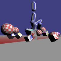
The simulation now contains a number of cubes, spheres and cylinders all positioned one above the next and all ready to drop into view. However, there are a couple of other things we should consider before we start running the simulation.
Friction
There is one important property shared by spheres and cylinders that does not apply to cubes: they roll. By default, Tokamak will not apply any friction or other damping force to rolling objects, so they will continue to roll or spin forever. This can create some "spinning-top"-like effects with cylinders, which will spin for hours around the floor, but this is not very realistic for a real-life simulation.
A simple friction can be applied to the objects using the
SetAngularDamping method of each rigid body. This has the
effect of continually moving the spin of the object along all axes towards
zero. Because of this, rolling objects will gradually slow down until they
stop.
An important point to note however is that the angular damping applies to the object at all times, not just when it is touching the ground.
The InitPhysics code above sets the angular damping to
0.01f for both the spheres and cylinders. This value results in
the objects slowing down as they roll but doesn't visibly affect the objects
while they are in motion in the air. Smaller values for this parameter will
cause the objects to decrease in speed more slowly. Larger values will cause
this to occur more quickly, but may have noticeable effects such as stopping
the objects from spinning while they are in mid-air.
Bounciness
The final property to look at in this tutorial is the "bounciness" of objects in the simulation. Bounciness can be controlled by creating a material and assigning it to a body. Materials have two properties: friction and restitution.
Friction controls how much the movement of an external object is reduced when it collides with the material. It only has any effect when the objects actually collide and bounce, however: once the object has stopped bouncing and is rolling, this parameter has no effect (though according to the Tokamak team, this is a bug which should be fixed in a future release of the library). For this reason we still need to use the angular damping described above.
Restitution is the property that controls how high objects will bounce. When two objects collide, the restitution values of the two objects are added together and the resulting value is used to calculate how they bounce against one another. It is therefore possible to use a negative value for restitution for one object to cancel out the restitution of another. A resulting value less than or equal to zero will not cause any bounce at all.
Materials are created by calling the SetMaterial method of
the simulator object. The method expects a material ID to be passed as the
first parameter. If an ID is passed that has not previously been used, a new
material will be created using that ID. The remaining parameters are used to
pass the friction and restitution for the material.
A material with ID zero is created automatically by the Tokamak engine and is assigned to all bodies when they are first created. It has a friction value of 0.4, and a restitution of 0.5.
Materials can be assigned to a body using the
SetMaterialIndex method of the neGeometry object.
Once the material has been created as described above, simply pass its index
to this function.
In our simulation we will increase the bounciness of the floor by assigning a material to its geometry. The code to achieve this is as follows:
// Create an animated body for the floor gFloor = gSim->CreateAnimatedBody(); // Add geometry to the floor and set it to be a box // with size as defined by the FLOORSIZE constant geom = gFloor->AddGeometry(); boxSize1.Set(FLOORSIZE, 0.2f, FLOORSIZE); geom->SetBoxSize(boxSize1[0],boxSize1[1],boxSize1[2]); gFloor->UpdateBoundingInfo(); // Set the material for the floor gSim->SetMaterial(MATERIAL_FLOOR, 0.4f, 1.3f); geom->SetMaterialIndex(MATERIAL_FLOOR); // Set the position of the box within the simulator pos.Set(0.0f, -3.0f, 0.0f); gFloor->SetPos(pos);
Note that this only increases the bounciness of the floor, not of any of
the other objects. To change their bounciness either create a second
material to assign to them, or use SetMaterial to change
properties of the material with index zero, which will affect all objects in
the simulation unless a different material index has been applied to
them.
Spice it up
Just to make the simulation a bit more interesting to look at, we do two
more things in the Render procedure. The first thing we'll do
is to slowly swing the camera around the origin of the render space.
D3DXMATRIX view_matrix; D3DXMatrixLookAtLH(&view_matrix, &D3DXVECTOR3( sinf(gfCameraAngle*0.2f)*25, 10.0f, cosf((gfCameraAngle+0.1f)*0.25f)*25 ), &D3DXVECTOR3( 0.0f, 0.0f, 0.0f ), &D3DXVECTOR3( 0.0f, 1.0f, 0.0f )); gD3DDevice->SetTransform(D3DTS_VIEW,&view_matrix); // Update the camera angle gfCameraAngle += fElapsed;
If you prefer a fixed camera position, remove these lines of code.
Finally, we'll periodically reset the simulation so that all object positions are reinitialised. This allows the simulation to run again and again without any user intervention. Resetting the simulation is achieved quite simply by destroying the Tokamak simulator (which clears all of its objects) and then reinitialising it all again.
// Periodically reset the object positions gfSceneTime += fElapsed; if (gfSceneTime > 20) { KillPhysics(); InitPhysics(); gfSceneTime = 0; }
That concludes this tutorial. The source code and a compiled executable for this tutorial are available in the following .zip file.

TokamakTutorial3.zip
| << Tutorial 2, colliding cubes << | >> Tutorial 4, terrain mesh >> |
If you have any comments or suggestions regarding this article, please don't hesitate to contact me.
This article is copyright © Adam Dawes, 2003.
It may not be copied or redistributed without my express written permission.