Tutorial 4, terrain mesh
Up until now, we've dropped our rigid bodies over a flat floor formed by a single animated body. Tokamak allows us to create much more complex surfaces, however, known as a Terrain Mesh.
A terrain mesh is a set of triangles that are used to determine the shape of the ground onto which your rigid bodies will fall. It isn't limited to just the ground, of course; you could use it to form the walls and ceiling of a room too, or even the roads and buildings of a city. It is commonly used to form hills and valleys or landscapes, though, and hence the name "terrain" mesh.
Unlike an animated body (which can only be composed of the standard Tokamak primitives -- cubes, spheres and cylinders) a terrain mesh can be any shape at all. Although you can only have a single terrain mesh, there's no need for all of the triangles to touch one another, so the mesh could have any number of independent sections.
The terrain mesh can also be as large and complex as you like, but (of course) the more complex your mesh becomes, the more processing time Tokamak will require in order to determine if anything has collided with it. For very complex meshes, a better approach is to use a callback function to provide more specific control over mesh collisions. This callback will be examined in a later tutorial.
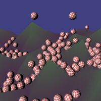
In this tutorial we will construct a random "landscape" and drop a number of spheres from above in order to see how they interact with the terrain.
How are we building our terrain mesh?
We'll create our landscape as a grid of squares. Each square will of course be divided into two as Tokamak's terrain mesh is defined using triangles. As mentioned above, the mesh can be any shape you require, there's no need to stick to the rigid grid approach I'm using here.
The basic layout of our mesh will be as follows:
Although the quads within the mesh form a 3x3 grid, the mesh is actually a 4x4 mesh as we need to define the positions of the vertices rather than the positions of the triangles. Also note that we're using the x and z axes to represent the top-down view of the mesh, as we'll use the y-axis to represent the height of each of our mesh nodes. With the heights applied to the y-axis and the terrain rendered with a perspective projection, this is the type of thing we'll be trying to produce:
Let's get started with the code. First of all, we'll define two constants to define the number of vertices along the x and z axes.
// Terrain vertex details #define TERRAINX 4 #define TERRAINZ 4
The sample provided with this tutorial uses a larger mesh than this, but it is simply a matter of adjusting these two constants.
Next we'll define a couple of calculated constants that let us easily determine how many vertices and triangles there are within our mesh. We will need these both when we're generating and drawing the mesh so it makes sense to define these calculations just once. We also define the size of the terrain (how far across the x and z axes the mesh extends) and the maximum height of each of the terrain vertices.
// The terrain vertex count is simply the number of height nodes we have #define TERRAIN_VERTEXCOUNT (TERRAINX * TERRAINZ) // The triangle count is the number of quads (which is one // less than each dimension of the terrain vertex map) multiplied // by two (as we need two triangles to make up each quad). #define TERRAIN_TRIANGLECOUNT ((TERRAINX-1)*(TERRAINZ-1)*2) // The size (x- and z-axes) and height (y-axis) for the terrain #define TERRAINSIZE 25.0f #define TERRAINHEIGHT 10
Finally for this section of code, an array of floats to hold the heights
of each vertex. For the tutorial we will just fill this array with random
values (in the SetTerrainHeights() function later on), but if
you wanted to design your own mesh you could pre-load the array values here
instead of setting them up in code.
float gfTerrainHeights[TERRAINX][TERRAINZ];
Defining the mesh
The terrain mesh is created using an neTriangleMesh object.
Once initialised, this is simply passed to the Tokamak simulator using the
SetTerrainMesh() function instead of setting up the animated
body that would previously have formed the floor. In the sample code, this
takes place in the BuildTerrainMesh() function, which is called
from within InitPhysics. This section will focus on how to
initialise the neTriangleMesh object.
The object has four members:
neV3 *vertices; s32 vertexCount; neTriangle *triangles; s32 triangleCount;
The vertices member is a pointer to an array of
neV3 objects. This is just a type that can be used to store an
x, y and z position, and so this is what we will use to store the positions
of each vertex that makes up the triangle mesh. Note that these are absolute
positions in space; a terrain mesh cannot be translated, scaled or rotated
in the way that an animated body can.
vertexCount simply allows us to tell Tokamak how many items
are present within the vertices array.
triangles is a pointer to an array of
neTriangle objects. Each triangle is defined by referencing the
vertices that we have provided in the vertices array. The
neTriangle objects will be examined in more detail when we get
to the code that builds this array shortly.
triangleCount allows us to tell Tokamak how many triangles
are present within the triangles array.
Once we've fully populated the members of this object, we can pass it to
Tokamak ready for it to use. BuildTerrainMesh() begins as
follows. After declaring the variables we are going to use, we call into
SetTerrainHeights() in order to generate some random height
values for each of our terrain vertices.
void BuildTerrainMesh(void) { int iTriIndex; float fTerrainX, fTerrainZ; int x,z; // Declare a terrain mesh for the floor neTriangleMesh triMesh; // The array of vertices neV3 triVertices[TERRAIN_VERTEXCOUNT]; // The array of triangles neTriangle triData[TERRAIN_TRIANGLECOUNT]; // First set the terrain node heights SetTerrainHeights();
Setting the number of vertices is easy, we already defined a constant for this value above.
// Set the number of vertices into the triMesh triMesh.vertexCount = TERRAIN_VERTEXCOUNT;
Next we need to calculate the position for each vertex. We'll loop on the
x and z axes in order to cover each vertex. To calculate the x and z
position we'll use two variables, fTerrainX and
fTerrainZ, which we'll update after each iteration of the loop
to ensure they're in the right place. They will start at half the terrain
size one side of each axis and will be increased until they are half the
terrain size on the other side, making the total size equal to the defined
terrain size.
All we do within the loop is set the coordinate of each vertex, using the
x and z positions from our loop and the y position from our
gfTerrainHeights array. We are building the vertex array as a
one-dimensional array rather than using two dimensions. The reason for this
is that we will later need to specify an index for each vertex, and we are
only able to use a single number for this. To build the two-dimensional data
into a one-dimensional array, we multiply the z array index by the number of
elements in the x part of the array (TERRAIN_X), resulting in
the index being calculated as follows:
x z result 0 0 0 + (0*4) = 0 1 0 1 + (0*4) = 1 2 0 2 + (0*4) = 2 3 0 3 + (0*4) = 3 0 1 0 + (1*4) = 4 1 1 1 + (1*4) = 5 2 1 2 + (1*4) = 6 3 1 3 + (1*4) = 7 0 2 0 + (2*4) = 8 ... ... ... 2 3 2 + (3*4) = 14 3 3 3 + (3*4) = 15
At the end of the loop, we put the address of the array into the triangle
mesh's vertices member.
// Set the vertex values fTerrainZ = -TERRAINSIZE/2; for (z=0; z<TERRAINZ; z++) { fTerrainX = -TERRAINSIZE/2; for (x=0; x<TERRAINX; x++) { triVertices[x + z*TERRAINX].Set(fTerrainX, gfTerrainHeights[x][z], fTerrainZ); fTerrainX += (TERRAINSIZE / (TERRAINX-1)); } fTerrainZ += (TERRAINSIZE / (TERRAINZ-1)); } // Set the vertices into the triMesh triMesh.vertices = triVertices;
That's the vertices set, next we have to tell Tokamak how to join them
together to make up the triangles that will form the mesh. The first part is
to set the number of triangles into the triangleCount property
of the triangle mesh:
// Set the number of triangles into the triMesh triMesh.triangleCount = TERRAIN_TRIANGLECOUNT;
Next we provide the triangle data itself. The indices are provided to Tokamak using an array of neTriangle objects, which we'll then set into the triangle mesh. Each triangle is defined by specifying the vertex indices that form the three corners of the triangle. The way we have set up our vertex array means that the vertices are numbered as follows:
To define the first triangle, we therefore provide vertex indices 0, 1 and 4. The matching triangle that completes the first quad uses indices 1, 4 and 5. The second pair of triangles uses vertex indices 1, 2 and 5, and then 2, 5 and 6.
The next block of code loops through our terrain to determine the vertex
indices required to create each triangle. In addition to these indices we
also set the material that we want to use for each triangle, and a "flag"
value. The flag must always be set to
neTriangle::NE_TRI_TRIANGLE. Once we've constructed the array,
we put its address into the triangles property of the triangle
mesh.
// Set the triangle values iTriIndex = 0; for (x=0; x<TERRAINX-1; x++) { for (z=0; z<TERRAINZ-1; z++) { // Make the triangle for the first half of the quad triData[iTriIndex].indices[0] = x + z *TERRAINX; triData[iTriIndex].indices[1] = x + (z+1)*TERRAINX; triData[iTriIndex].indices[2] = (x+1) + z *TERRAINX; triData[iTriIndex].materialID = 0; triData[iTriIndex].flag = neTriangle::NE_TRI_TRIANGLE; // Move to the next triangle in the array iTriIndex += 1; // Make the triangle for the second half of the quad triData[iTriIndex].indices[0] = x + (z+1)*TERRAINX; triData[iTriIndex].indices[1] = (x+1) + (z+1)*TERRAINX; triData[iTriIndex].indices[2] = (x+1) + z *TERRAINX; triData[iTriIndex].materialID = 0; triData[iTriIndex].flag = neTriangle::NE_TRI_TRIANGLE; // Move to the next triangle in the array iTriIndex += 1; } } // Set the triangles into the triMesh triMesh.triangles = triData;
It should be noted that terrain triangles are double-sided, the vertices do not have to be wound in any particular direction (clockwise/anti- clockwise) in order for the terrain triangle to count.
The triangle mesh is now fully populated, so we can finally pass it to Tokamak for it to use.
// Tell the simulator about our mesh gSim->SetTerrainMesh(&triMesh);
It's not much good if we can't see the terrain though. Tokamak now knows all about it, but we've not told DirectX anything yet.
In all of these tutorials I'm trying to keep the Tokamak code and the DirectX code as far apart as possible. This is so that the Tokamak code can be seen clearly without any graphics API complexity, and also because I want these tutorials to be easily converted to work with other graphics APIs such as OpenGL. For this reason I haven't build the DirectX vertex buffer in the loops shown above. In a "real" application, this may have been a more efficient way to build the vertex data. However, I don't want to have to do all that calculation again (it's increased complexity and a chance that the Tokamak and DirectX views of what the terrain look like may get out-of- step). To generate the DirectX buffers as easily as possible I'm going to read the values back from the triangle mesh.
This is achieved in the BuildTerrainDX() function. I won't
go into great detail about this function as it's nothing to do specifically
with Tokamak, but as a quick overview I decided to use indexed primitives to
render the terrain in this program. The concept is virtually identical to
that used within the triangle mesh: we define a series of vertices (these go
in the vertex buffer) and a series of triangles (constructed using the
vertex indices). This means we can pretty much read the values straight out
of the triangle mesh and into the index and vertex buffers.
For more information, take a look at the function in the code sample. The code comments should make it clear what's happening.
The last new function is a small one: SetTerrainHeights(),
as called at the beginning of BuildTerrainMesh(). This simply
applies a random height value to each entry in the
gfTerrainHeights array. If you wanted to try creating a more
interested algorithmic landscape, this is the place to put your code.
Rendering
We're nearly finished now, the simulator is ready to run, but there are a
couple more changes to be made within the Render()
function.
One thing that happens frequently with this simulation is that the spheres fall off the side of the landscape. Sometimes, in fact, the landscape will funnel the spheres over the side, causing them to all fall out of the scene. To stop things getting very empty, we'll catch the spheres that fall and replace them above the terrain so that they can fall onto it again.
Finding the spheres that have fallen is easy: we simply check the 2nd
element (which corresponds to the y axis) of the pos array
within the transformation matrix returned by the rigid body's
GetTransform() call. If this value gets too low we reset the
position of the sphere using the SetPos() method.
Simply resetting the position isn't sufficient though, as the sphere will
retain the velocity and angular momentum (spin) from before we moved it.
This will mean it is initially falling very quickly, which isn't what I want
to achieve. To cancel out these properties we call the
SetVelocity() method with a vector containing the values
[0,0,0] (which means the velocity will be zero on each axis), and then
SetAngularMomentum() with another vector containing [0,0,0]
(which means that the spin is reduced to zero on each axis). This leaves the
sphere perfectly stationary at the moment of initialisation.
// Check the Y-position of the sphere. // If it falls too low then the sphere has fallen off of the floor; // we'll re-drop it if this occurs to keep things moving. if(t.pos[1] < -25) { // Reset the position of the sphere pos.Set((float)(rand()%10)-4, 20, (float)(rand()%10)-4); gSpheres[i]->SetPos(pos); // Reset the velocity (so it doesn't already have a downward momentum from before) vel.Set(0,0,0); gSpheres[i]->SetVelocity(vel); // Reset the angular momentum (so it isn't spinning from before); spin.Set(0,0,0); gSpheres[i]->SetAngularMomentum(spin); }
The last new piece of code is required to render the terrain itself. This
simply sets the vertex and the index buffer, and then calls DirectX's
DrawIndexedPrimitive method. The number of vertices and
triangles are known from the constants we defined right back at the
beginning.
// Set the vertex and index stream for the floor gD3DDevice->SetStreamSource(0,vbFloor,sizeof(strVertex)); gD3DDevice->SetIndices(ibFloor, 0); // Reset the view matrix to the identity matrix dxLoadIdentity(); dxApplyMatrix(gD3DDevice); // Draw the floor gD3DDevice->DrawIndexedPrimitive(D3DPT_TRIANGLELIST, 0, TERRAIN_VERTEXCOUNT, 0, TERRAIN_TRIANGLECOUNT);
Now run the code and see how it looks. Doesn't that just inspire you to write a mini-golf game, or a new version of Marble Madness?
That concludes this tutorial. The source code and a compiled executable for this tutorial are available in the following .zip file.

TokamakTutorial4.zip
| << Tutorial 3, cylinders and spheres << | >> Tutorial 5, terrain callback >> |
If you have any comments or suggestions regarding this article, please don't hesitate to contact me.
This article is copyright © Adam Dawes, 2004.
It may not be copied or redistributed without my express written permission.